

 Previous
LEAVE A REPLY
Your email address will not be published.Required fields are marked *

1. Overview
In this tutorial, we will learn how to use Arduino code to implement CANBUS communication with DHT11 sensor. We will also using an OLED in this project, so we can display the temperature and humidity on it.
2. Bills of Materials
2.1 Hardware:
• Maduino Zero CANBUS
• DHT11 Temperature& Humidity Module
• 1.3" I2C OLED 128x64- Blue
• DB9 to DB9 cable (female to female)
• Dupont Line
2.2 Software:
• Arduino IDE
3. What Is CANBUS
3.1 About CAN
CAN (Controller Area Network) is a serial communication network that can realize distributed real-time control. It is developed for the automotive industry to replace the complex wiring harness with a two-wire bus.
CAN protocol defines the Data Link Layer and part of the Physical Layer in the OSI model.
The CAN protocol is ISO standardized with ISO11898 and ISO11519. ISO11898 is the CAN high-speed communication standard with a communication speed of 125kbps-1Mbps. ISO11519 is the CAN low-speed communication standard with a communication speed of less than 125kbps.
Here we focus on high-speed CAN.
• ISO-11898 describes how information is passed between devices on a network and conforms to the Open Systems Interconnection model(OSI) that is defined in terms of layers. The actual communication between devices connected by the physical medium is defined by the physical layer of the model.
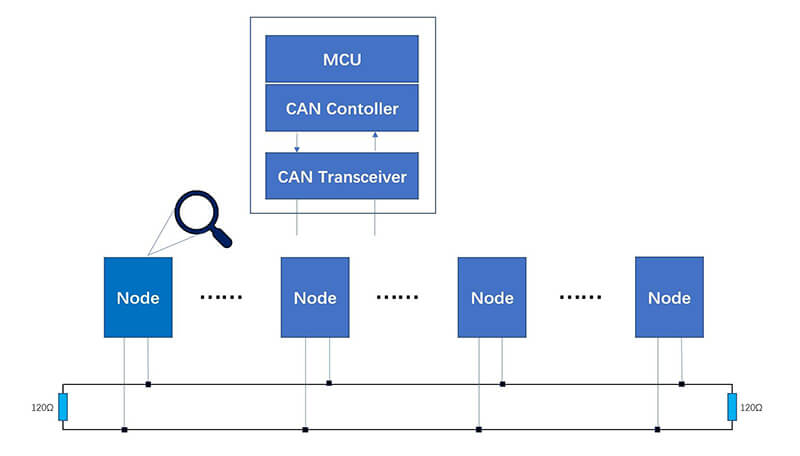
• Each CAN unit connected to the bus can be called a node. All CAN units are connected to a bus terminated at each end with 120 Ω resistors to form a network. The bus consists of CAN_H and CAN_L lines. The CAN controller determines the bus level based on the difference in the power level on both wires. Bus levels are divided into dominant and recessive levels, which must be one of them. The sender sends the message to the receiver by making a change at the bus level. When the logical line "and" is executed on the bus, the dominant level is "0" and the recessive level is "1".
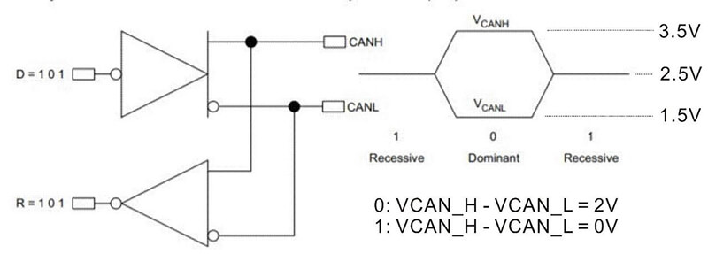
• In the dominant state, the voltage of CAN_H is about 3.5V and the voltage of CAN_L is about 1.5V. In the recessive state, the voltage of both lines are around 2.5V.
• The signal is differential that is why CAN derives its robust noise immunity and fault tolerance. Balanced differential signal reduces noise coupling and allows for high signaling rates over twisted-pair cable. The current in each signal line is equal but in the opposite direction and resulting in a field-canceling effect that is key to low noise emissions. The use of balanced differential receivers and twisted-pair cabling enhances the common-mode rejection and high noise immunity of a CAN bus.
3.2 CAN Transceiver
The CAN Transceiver is responsible for the conversion between the logic level and the physical signal. Convert a logical signal to a differential level or a physical signal to a logical level.
3.3 CAN Controller
The CAN Controller is the core component of CAN, which realizes all the functions of the data link layer in CAN protocol and can automatically resolve CAN protocol.
3.4 MCU
The MCU is responsible for the control of the function circuit and the CAN controller. For example, the CAN controller parameters are initialized when the node starts, the CAN frame is read and sent through the CAN controller, etc.
4. CAN Communications
When the bus is idle, all nodes can start sending messages (multi-master control). The node that first accesses the bus gets the right to send (CSMA/CA mode). When multiple nodes start sending at the same time, the node that sends the high priority ID message gets the right to send.
In the CAN protocol, all messages are sent in a fixed format. When the bus is idle, all units connected to the bus can start sending new messages. When more than two cells start sending messages at the same time, the priority is determined based on the identifier. The ID does not represent the destination address of the send, but rather the priority of the message accessing the bus. When more than two cells start sending messages at the same time, each bit of the interest-free ID is arbitrated one by one. The unit that wins the arbitration can continue to send messages, and the unit that loses the arbitration immediately stops sending and receives the work.
The CAN bus is a broadcast type of bus. This means that all nodes can ‘hear’ all transmissions. all nodes will invariably pick up all traffic. The CAN hardware provides local filtering so that each node may react only to the interesting messages.
5. Frames
CAN devices send data across the CAN network in packets called frames.
CAN has four frame types:
• Data frame: a frame containing node data for transmission
• Remote frame: a frame requesting the transmission of a specific identifier
• Error frame: a frame transmitted by any node detecting an error
• Overload frame: a frame to inject a delay between data or remote frame
5.1 Data frame
There are two types of data frames, standard and extended.
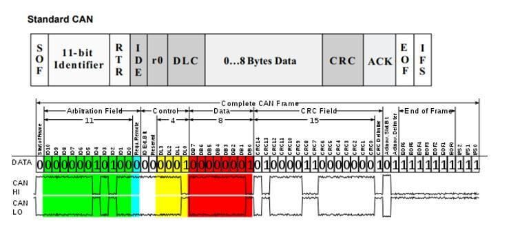
The meaning of the bit fields of the Figure are:
• SOF -- The single dominant start of frame (SOF) bit marks the start of the message, and is used to synchronize the nodes on a bus after being idle.
• Identifier -- The Standard CAN 11-bit identifier establishes the priority of the message. The lower the binary value, the higher its priority.
• RTR -- The single remote transmission request (RTR) bit
• IDE -- A dominant single identifier extension (IDE) bit means that a standard CAN identifier with no extension is being transmitted.
• R0 -- Reserved bit (for possible use by future standard amendment).
• DLC -- The 4-bit data length code (DLC) contains the number of bytes of data being transmitted.
• Data -- Up to 64 bits of application data may be transmitted.
• CRC -- The 16-bit (15 bits plus delimiter) cyclic redundancy check (CRC) contains the checksum (number of bits transmitted) of the preceding application data for error detection.
• ACK -- ACK is 2 bits, one is the acknowledgment bit and the second is a delimiter.
• EOF -- This end-of-frame (EOF), 7-bit field marks the end of a CAN frame (message) and disables bitstuffing, indicating a stuffing error when dominant. When 5 bits of the same logic level occur in succession during normal operation, a bit of the opposite logic level is stuffed into the data.
• IFS -- This 7-bit interframe space (IFS) contains the time required by the controller to move a correctly received frame to its proper position in a message buffer area.
5.2 Arbitration
In the bus idle state, the unit that starts sending the message first gets the sending right. When multiple units start sending at the same time, each sending unit starts at the first bit of the arbitration segment. The unit with the largest number of continuous output dominant levels can continue to send.
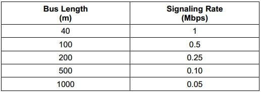
6. Canbus Communication Speed and Distance
The CAN bus is a bus that connects multiple units at the same time. There is theoretically no limit to the total number of units that can be connected. In practice, however, the number of units that can be connected is limited by the time delay on the bus and the electrical load. Reduce the speed of communication, increase the number of units that can be connected, and increase the speed of communication, the number of units that can be connected decreases.
The communication distance is inversely related to the communication speed, and the farther the communication distance, the smaller the communication speed. The longer distance can be 1km or more, but the speed is less than 40kps.
7. Maduino Zero Canbus by Makerfabs
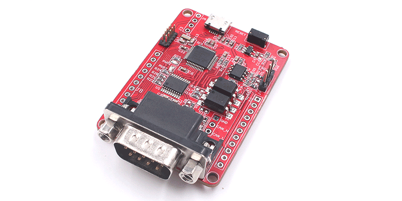
Maduino Zero CAN-BUS module is a tool developed by Makerfabs for CANbus communication, it's based on Arduino, with the CAN controller and CAN transceiver, to create a ready-to-use CAN-bus port.
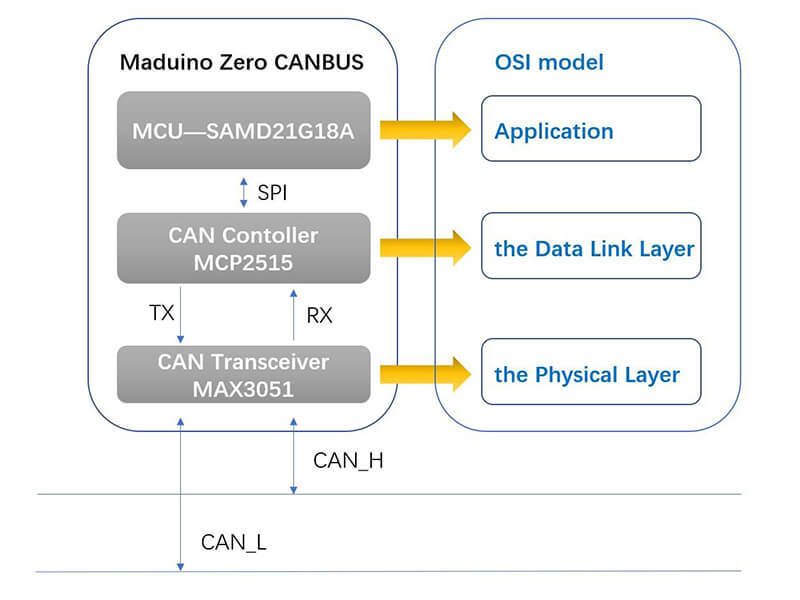
• MCP2515 is a stand-alone CAN controller that implements the CAN specification. It is capable of transmitting and receiving both standard and extended data and remote frames.
• The MAX3051 interfaces between the CAN protocol controller and the physical wires of the bus lines in a controller area network (CAN). The MAX3051 provides differential transmit capability to the bus and differential receive capability to the CAN controller.
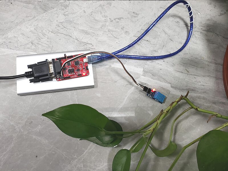
8. Connection
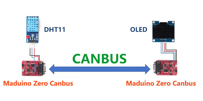
Connect the DHT11 module to the Maduino Zero CAN-BUS module with wires to be used as an instrument to support CAN communication. Similarly, connect the display to the module to receive the data and display it.
The connection between Maduino Zero CANBUS and DHT11:
| Maduino Zero CANBUS -- DHT11 3v3 ------ VCC GND ------ GND D10 ------ DATA |
The connection between Maduino Zero CANBUS and OLED:
| Maduino Zero CANBUS -- OLED 3v3 ------ VCC GND ------ GND SCL ------ SCL SDA ------ SDA |
Use a DB9 cable to connect the two Maduino Zero CANBUS modules.
9. Code
The MAX3051 completes the conversion of differential levels to logical signals. The MCP2515 completes CAN function such as data encoding and decoding. The MCU only needs to initialize the controller and send and receive data.
• Github: https://github.com/Makerfabs/Maduino-CANbus-RS485/tree/main/Test_DHT11_OLED
• After installed Arduino, there is no package to support the board (Arduino zero) that is needed to be installed.
• Select tools --> Board --> Board Manager, search "Arduino zero" and install "Arduino SAMD Boards".
• Select Tools --> Board --> Arduino Zero (Native USB Port), select Tools --> Port --> com…
• After getting the program from GitHub, you need to make sure that all files are in the project directory, which contains library files that support CANBUS.
• Install the DHT sensor library by Adafruit, which is used to drive the DHT11 to obtain temperature and humidity.
• Use different addresses to send temperature and humidity separately in the code Test_DHT11.ino.
| CAN.sendMsgBuf(0x10, 0, stmp1.length(), stmp_send1); delay(500); CAN.sendMsgBuf(0x11, 0, stmp2.length(), stmp_send2); delay(500);<br> |
"0x10" is mean the message ID, "0" is mean standard frame, "stmp1.length()" is mean the message length, "stmp_send1" is the data sent.
• In the code Test_OLED.ino, all messages on the CANBUS are received by query and the required information is displayed on the OLED.
• Upload the program Maduino-CANbus-RS485/Test_DHT11_OLED/Test_DHT11/Test_DHT11.ino to the module which connected to the sensor, and Upload the program Maduino-CANbus RS485/Test_DHT11_OLED/Test_OLED/Test_OLED.ino to another module which connected to the OLED.
10. Result
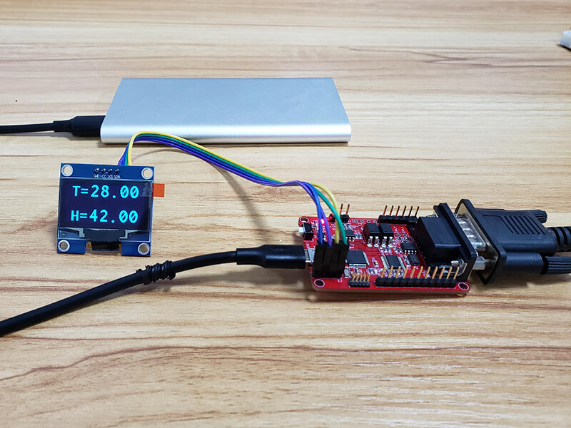
Power on the two modules, temperature and humidity will be displayed on the display.
If you have further questions based on this canbus project, or if you need some custom PCBA service based on those Maduino IoT solutions, feel free to let us know, pls contact service@makerfabs.com.


