

 Previous
LEAVE A REPLY
Your email address will not be published.Required fields are marked *

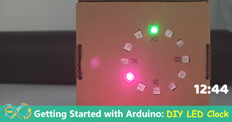
This is an Arduino tutorial for starters: Getting Started with Arduino, learn how to control a LED light, we will make a DIY LED clock.
Many times I woke up in the middle of the night and wanted to check the time. I need to turn on the lights or wake up the phone to view. When I turn on the light or phone, the light from the light or phone, dazzled me. I wanted to make a clock with the shimmer that can be placed in bedroom.
This tutorial shows how to light a NeoPixel LED and make a simple clock by 12 LED ring. I hope it is helpful for beginner to build a project.
1. Hardware Preparation
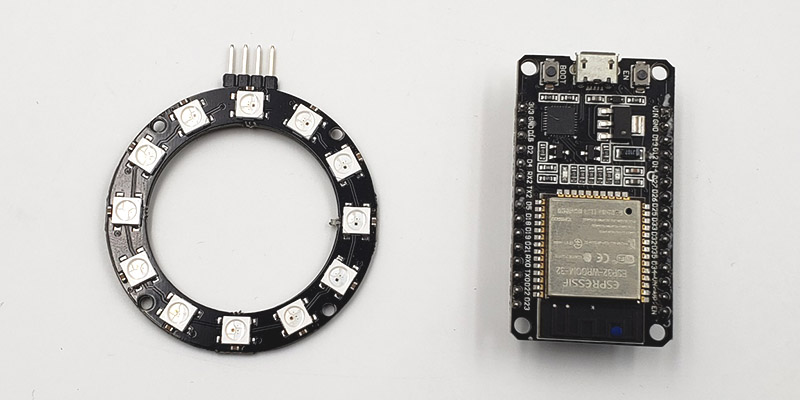
I have a ESP32 board and WS2812 LED ring in hand so I used for it. ESP32 can be replace by any Arduino board to light a LED. The WS2812 is also replaced by any WS2812 LEDs.
Here I use below 2 board, you can sourcing related boards as your preference:
1. WS2812 LED
2. ESP32 Development Board
1.1 The Connection for LEDS
One NeoPixel LED has 4 pins (VCC, GND, DI, DO). The wiring that many LED connect together is as the below figure.
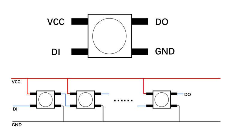
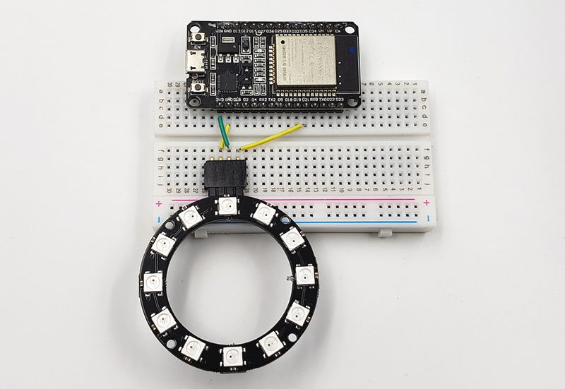
Whatever the number of LEDs connected, I can control them by connecting the three pins (VCC, GND, DI) to Arduino. The connection as the below:
• VCC connect to the 5V of the ESP32 board.
• GND connect to the GND of the ESP32 board.
• DI connect to the IO21 of the ESP32 board.
2. Software Preparation
1. Install Arduino ide to programming if you not install yet. Arduino IDE: https://www.arduino.cc/en/software.
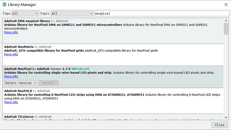
2. There are many libraries for neopixel led. I used the Adafruit one (Adafruit NeoPixel).
• Click the Tools option, select the "manage Library".
• Enter "neopixel" in the search box, then install the Adafruilt NeoPixel library.
3. Programming for Lighting the LED
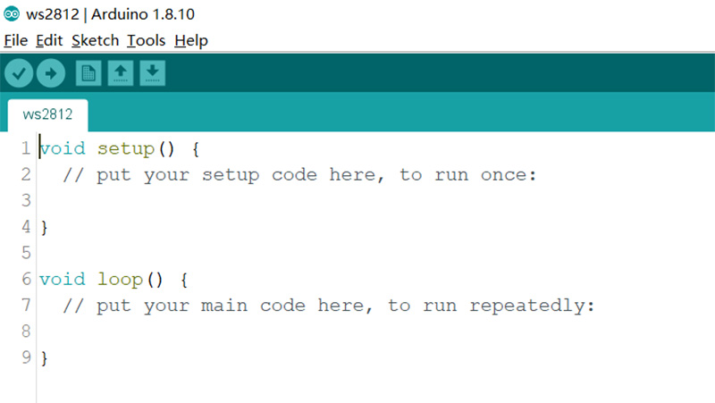
• Open Arduino and create a new file named WS2812.
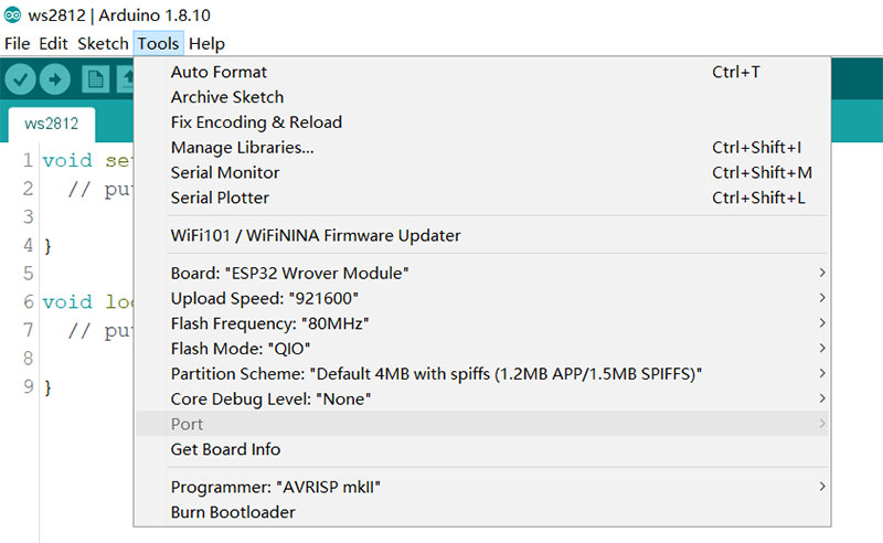
• Choose the board and port, the port can only be selected white the Arduino board is connected to PC.
• Add the library to the code
| #include <Adafruit_NeoPixel.h> |
• Define the pin number connected to LED, and define the number of connected LEDs.
| #define PIN 21 #define NUMPIXELS 12 |
• Define an object for the LEDs
| Adafruit_NeoPixel pixels(NUMPIXELS, PIN, NEO_GRB + NEO_KHZ800); |
• Innilize the LEDs in the setup code.
| pixels.begin(); |
• In the loop code, turn the LED to light green with 2s, then turn off with 1s.
| pixels.setPixelColor(2, pixels.Color(0, 70, 0)); pixels.show(); delay(2000); pixels.clear(); delay(1000); |
Code Explanation:
1. "setPixelColor()" is to set which the LED and which the color.
2. "2" is means the second LED to light.
3. "(0,70,0)" represent the green color, "(70,0,0)" represent the red, "(0,0,70)" represent the blue. The number can be change from 0 to 255.
4. "pixels.show()" is means send the updated pixel colors to the hardware.
5. "pixels.show()" is means set all pixel colors to 'off'.
• The program should be like below when it completed.
|
#include <Adafruit_NeoPixel.h> Adafruit_NeoPixel pixels(NUMPIXELS, PIN, NEO_GRB + NEO_KHZ800); void setup() { void loop() { |
• Upload the program to the Arduino board.

4. Project: DIY LED Clock
Next, I will introduce a project that I used the WS2812 ring to make a clock.
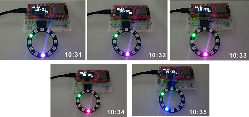
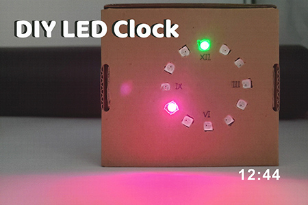
I wanted to get time from the internet and show it with the LED ring. If the LED ring is a clock, the LED lighted green will be the hour hand, the blue or red one will be the minute hand. Due to the need for networking, other Arduino boards cannot be used instead of ESP32.
4.1 Programing for ESP32
• The program can be obtained from: https://github.com/Makerfabs/Makepython-ESP32/tree/master/example/WS2812_clock
• Define the wifi name and password.
| const char *ssid = "Makerfabs"; const char *password = "20160704"; |
• Connect to the wifi
| WiFi.begin(ssid, password); while (WiFi.status() != WL_CONNECTED) { delay(500); Serial.print("."); } Serial.println(" CONNECTED"); |
• Set the time zone of your area and configure the time.
| const char *ntpServer = "120.25.108.11"; const long gmtOffset_sec = 8 * 60 * 60; //China+8 const int daylightOffset_sec = 0; configTime(gmtOffset_sec, daylightOffset_sec, ntpServer); |
• Get the time from the internet.
| if (!getLocalTime(&timeinfo)) { Serial.println("Failed to obtain time"); return; } int hour = timeinfo.tm_hour; int min = timeinfo.tm_min; int sec = timeinfo.tm_sec; int day = timeinfo.tm_mday; int mon = timeinfo.tm_mon + 1; |
• Turn on the LEDs.
| pixels.setPixelColor(hour_d, pixels.Color(10, 70, 0)); pixels.setPixelColor(min_d, pixels.Color(min_r*15+10, 0, (5-min_r)*15)); pixels.show(); delay(999); |
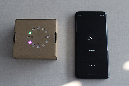
Here I use the MakePython ESP32 for the clock time calibration. If you use other ESP32 board in your project, it's easy to use your smartphone to check the LED clock:
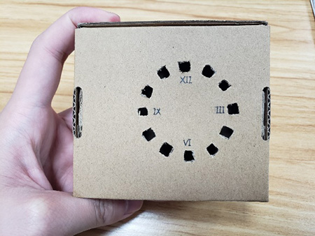
4.2 Make a Case for DIY LED Clock
I used the Carton that used to be a packaging box to package the LED ring. Frist, drill 12 holes on the carton surface. Then put all that includes a battery for power in the carton and assemble its. Draw on the case to decorate it. A real clock is completed.
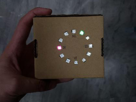
4.3 DIY LED Clock Finished!
After making the clock, I can tell the time by distinguishing the light. If the brightness of the light is still too strong, I can adjust it through the program, or stick a piece of paper on the surface of the clock.
If you have further questions for this Arduino tutorial or need some customized PCBA service, pls contact service@makerfabs.com .


